2014-06-30 – This (both this post, and the project) is a work in progress. My lights are installed and controllable, the installation is being upgraded, and a better user interface is needed.
Wanted to get into some electronics, and I really need some form of end objective to get going on anything. The thermostat project that was going to be my debut into electronics and microcontrollers has a pretty ambitious scope that has been intimidating enough to procrastinate any serious work on.
When I saw the advertisement form sparkfun with some addressable RGB LED strips for sale (60 WS2812 pixels/m) – I decided to do something with those. With solution in mind, I went looking for a problem.
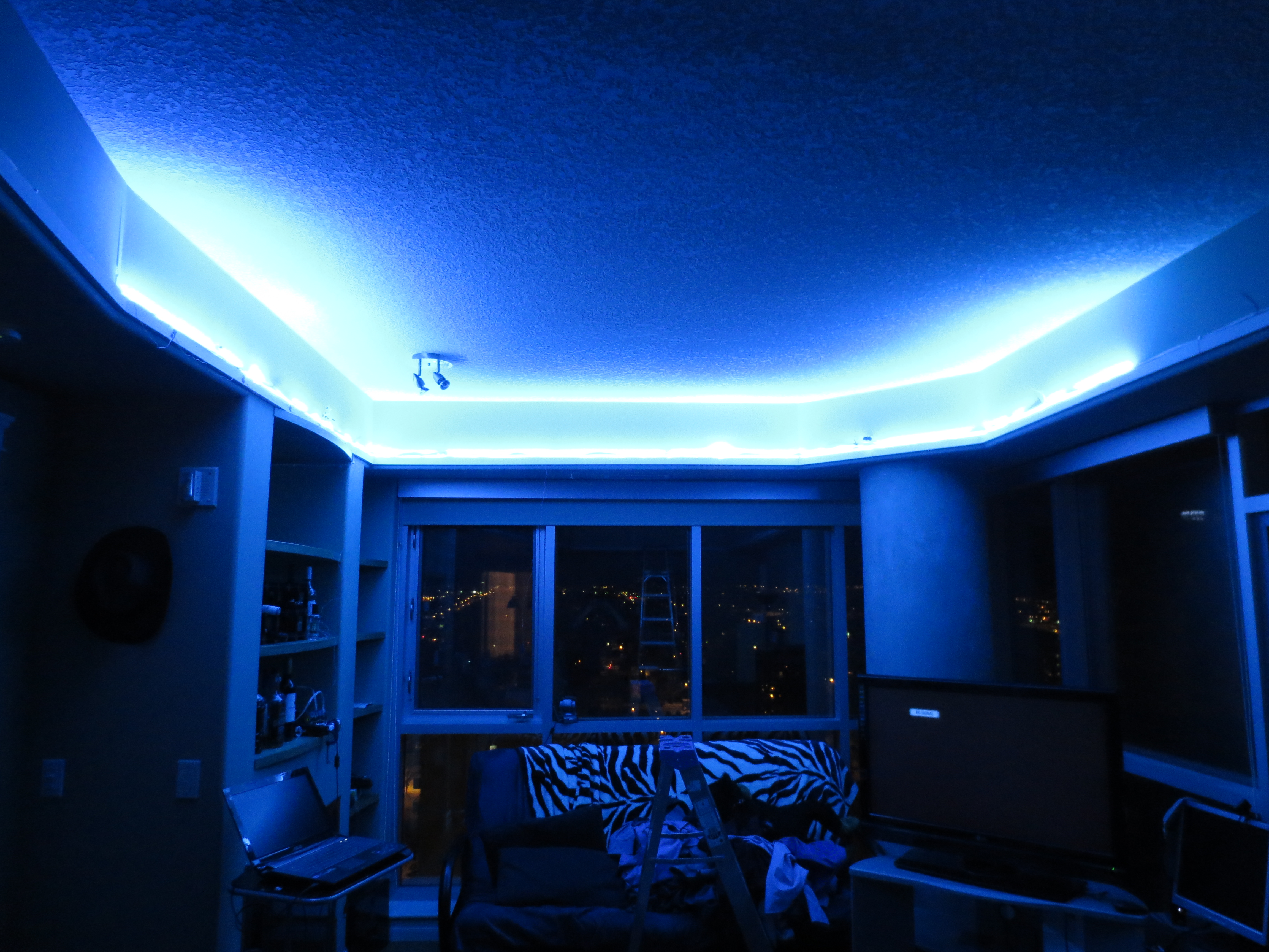
The crown around my living room has a perimeter around 17m, and I wanted some better lighting in there. At 60pixels/m, 1000 pixels works out to be a nice arbitrary round number that takes up enough space.
A test installation of a few strips from January:
Memory limitations
The whole point of having addressable LEDs is to be able to address each pixel individually! It turns out that little microcontrollers, at least the ones on the arduino boards that I own have some tight memory limitations.
The ATMEGA328P has 2kB of SRAM. Assuming the entire thing is dedicated to pixel colour data goodness (not the case, but good for a feel of scale) – it is going to max out at 682 pixels and you get one 16-bit int left over to play with. The code to create the control signal in the adafruit library is done in assembly and uses NOOP timing to achieve the right output for the protocol. It sucks in the RAM and dumps it down the wire, there are not extra CPU cycles to put new data into memory as the old is sent out.
??? < 682 pixels < 1000 pixels = pixels it can actually manage. So it’s not possible to individually control 1000 WS2812 pixels with an ATMEGA328P alone. At least not all in one shot. You can use a common control signal (and lose the ability to control each individual pixel), or use a shift register to change which control wire is being supplied for each strip refresh.
I divided my installation up into 5×200 pixel strips, modified the library a little bit, and use 5 pins for control output. The 200 number was arrived at after experimenting with one of the 5m 300 pixel strips.
This division turned out to also work well for the power distribution – no need to worry about keeping two parallel power supplies from fighting.
After the fact, I’m starting to think I’d like to be able to read frames from an SD card. SD Card is going to need 512 bytes of SRAM just for a buffer which might be too much. Now wouldn’t it be cool if one could use the exact same chunk of memory to read the card then feed the strip…. This project still needs some form of reasonable UI (right now control is serial over USB), SD card animations will be a project for some other time.
Experimenting with a 300 pixel strip
- The last 50 pixels started misbehaving when trying to display high values of red (~240-255). Unclear if it is an issue with the signal channel, or if it was a power distribution problem. I had a separate power supply than the arduino board for powering the lights.
- Ran into memory problems when trying to send out the signal for more than 600 LEDs. While there was only a 300 pixel strip hooked up, the Arduino didn’t have any way of knowing that – and it was easy to see that it had jammed up.
- After modifying the adafruit library to be able to free() the memory between iterations – I was able to successfully send the control signal for 600 pixels on each of 4 output pins (2400 pixels!)
- You don’t get a fast refresh rate though. I don’t recall how I measured the delta time, but from my notes: Re-initializing 5 segments of 200 LEDs took 60-70ms. Initializing one strip and then outputting 200 pixels on 5 different output pins took 14ms. (this would mean having the same pattern on each of the 5 – you’d probably get about 1/5 the refresh time by using a common control channel)
Power Distribution
In the worst case (full on), these should pull 60mA per LED dye per pixel. Running at 5V, 1000 of these works out to 60A total. It would take some enormous cabling to handle 60A without melting down, so I ended up needing to figure out some power distribution.
Too many amps – increase voltage. Using a 24V power supply the full draw will be 12.5A, easily manageable by some spare 14 gauge house wiring which I had sitting around. Step down to 5V with five EHHD015A0A units from digikey – this way the strips of 200 would each have their own power supply and their own control channel, keeping them as nice modular units.
This kind of amperage has the potential to go south. I actually purchased a couple fire extinguishers before starting the power part of this, and also figured out some contingencies of how I would go about testing things and what to do if things didn’t work as planned. This included a couple rehearsals. It might sound over the top – but there is huge benefit in having done it if you need to react. It is even more critical to think potential hazards through when working alone.
The extinguisher purchase for home was something that I’d been procrastinating on, and this was a good catalyst to get it done. Training in using them was part of my requirements for work, highly recommended. While previous training sessions had only involved putting out pan fires – the latest round of training included the enlightening (for me) concept of using the extinguishing media as a heat shield to approach or get past a heat source. A fire extinguisher’s usefulness went up exponentially in my eyes after experiencing that.
I only burned one wire due to getting a polarity wrong. The datasheet wasn’t very clear about which side is UP on the EHHD015A0A boards and I picked the wrong side. The first bump test (on for a second, then off) was okay, but on the second longer run – there was smoke. It took an extra couple seconds or so to respond with the initial surprise/panic, but then pulled the power just like the plan.
I did have some inline fuses (that are installed now), but none were installed for this initial test to see if it works. One other near miss where the current limiting protection built into the main 24VDC power supply was tested when some exposed wires touched (bridging the +24V to the DC ground) after the strips were repositioned on the wall.
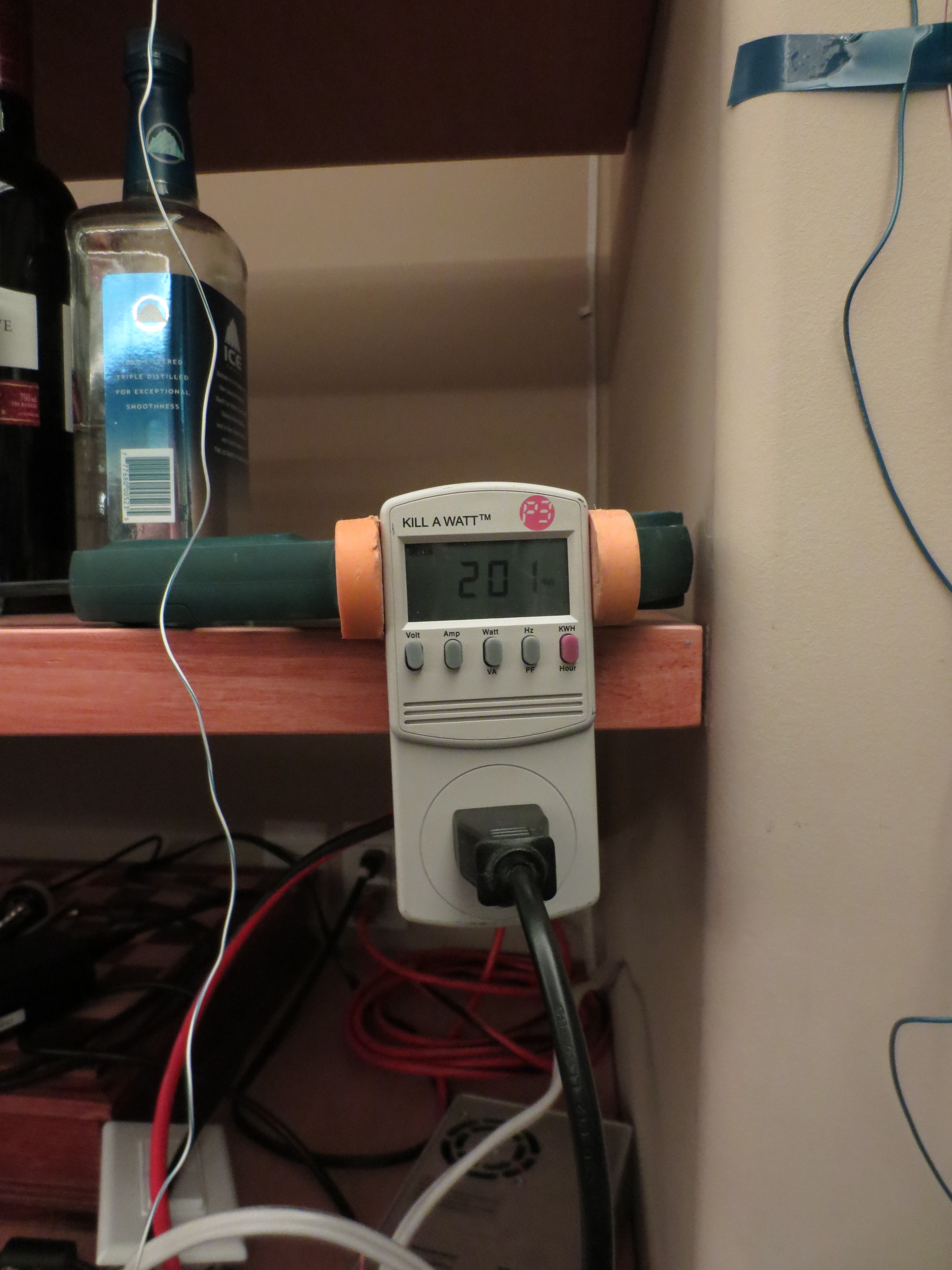
Measuring the power consumption. At full brightness on all lights, it pulls the expected 320W
EHHD015A0A Wiring details.
Programming – Adafruit Neopixel library
I made several tweaks to the adafruit neopixel library. Credit to Adafruit: https://github.com/adafruit/Adafruit_NeoPixel/archive/master.zip . I’m not really interested right now in trying to figure out GNU GPL terms conditions and responsibilities, so I won’t package and redistribute my modifications. There’s a link to the original library, and below are some of my tweaks to the code. Any of the code in this section that I have any IP rights to: I release as public domain.
Specifically – I added an eend() function to run free() on the currently allocated memory, added an initialization value for the brightness, and allowed changing of the output pin.
I noticed in the latest revision from Adafruit – they have added a setPin() function to their code that does the same thing as the changepin() that I added to mine! The only real difference in theirs vs. mine is that I don’t set the pinmode for the old pin back to INPUT.
Adafruit_Neopixel.cpp
void Adafruit_NeoPixel::begin(void) {
  pinMode(pin, OUTPUT);
  digitalWrite(pin, LOW);
  brightness=0;
}


// trying to find a way to clear the memory.
void Adafruit_NeoPixel::eend(void) {
  free(pixels);
  digitalWrite(pin, LOW);
//  pinMode(pin, INPUT);
}

void Adafruit_NeoPixel::changepin(uint8_t p) {
        pin = p;
        pinMode(pin, OUTPUT);
        digitalWrite(pin, LOW);
        port = portOutputRegister(digitalPinToPort(pin));
        pinMask = digitalPinToBitMask(pin);
}
Adafruit_Neopixel.h
public:

void
     ...
     eend(void),
     changepin(uint8_t p),
     ...
Voltage Spikes – oh no!
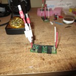
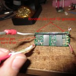
At least one of the lead pixels in each strip died in the process of getting this working. Not knowing what was going on, I put an oscilloscope on the end and saw some pretty significant voltage spikes at the end of the wire. I had also noticed that the strips would misbehave sometimes – displaying random colours for each pixel and sometimes the whole strip flickering on and off – and would straighten up when the control wire was making contact with my bare hands.
I did read somewhere that shorting out the digital line across the suspected bad pixel would work for troubleshooting it. This did not work in my case, nor did hooking the digital line to the second pixel’s input (and nothing to the first pixel’s). Don’t know why, but in each case the strip started working again after I amputated the failed first pixel.
-
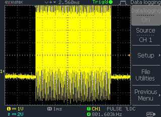
- no inline resistance
-
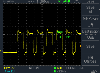
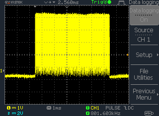
- 110ohm inline at the source
-
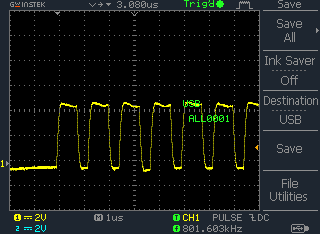
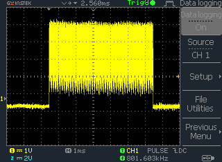
- 220ohm inline at the source
-
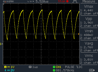
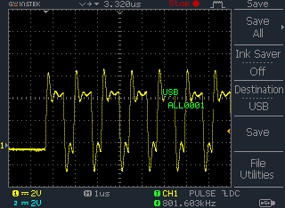
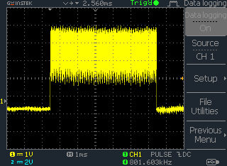
- 1080ohm inline at the source – note elevated DC level
Data channel voltage with respect to time measured at the strip data input location. Too little and there are some high voltage spikes, too much and the signal becomes too distorted for the WS2812 to recognize it.

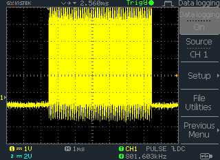
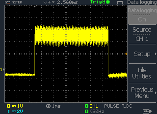
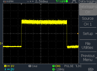
You can see the effect of resistance in the data line better from a wider time frame. A series of screenshots were captured on the scope while I adjusted a variable POT that was inline on the control channel.
I’m guessing this might be from an impedance mismatch – but whatever the cause installing some resistors in the control line at the source calmed the voltage spikes down significantly. There is probably an optimal RC filter that will take care of it, I just tinkered empirically until something seemed to work. The one longest control wire still has some control issues where the whole strip will randomly flicker random colours – but it behaves most of the time. I expect to improve more after I trim it’s wire down.

Disassembled a Cat5 ethernet cable for the signal wires. To untwist the pairs – I chucked the wires into my cordless drill and let ‘er rip.
Installation
The first iteration of installation involved installing a strip of 1x2s with the lights situated on top. Currently putting some 1×4 boards in front of the 1×2 – to give a bit of a gap to hide the wiring and power supplies behind.